Modbus
Modbus is a serial communication protocol developed in 1979 by Modicon (now Schneider Electric) for use with programmable logic controllers (PLCs). It has become a standard protocol for industrial communication due to its simplicity and reliability.
In essence, Modbus allows devices to communicate over various types of networks, including serial lines (Modbus RTU and Modbus ASCII) and Ethernet (Modbus TCP). It operates on a master/slave or client/server architecture, where the master (or client) sends requests to the slaves (or servers), which then respond with the requested data.
Modbus is widely used in industrial environments for connecting and transmitting data between devices like sensors, controllers, and computers. Energy meters are a classic example: almost every industrial energy meter speaks Modbus.

Is your Modbus RTU device far away from any PC, for example an energy meter in a cabinet? UpBlue Connect hardware can read it on the spot.
Basics
Modbus contains registers with addresses. Each register address contains 8 bits. An 8 bit value can not be more than 255. To overcome this low number, in Modbus you can combine multiple registers to form a number.
- Two 8 bit registers become 16 bit
- Four 8 bit registers become 32 bit
- Eight 8 bit registers become 64 bit
This represents:
| Order | Min | Max |
|---|---|---|
| 8 bit | -128 | 127 |
| 16-bit | -32.768 | 32.767 |
| 32-bit | -2.147.483.648 | 2.147.483.647 |
| 64-bit | -(9 x 10^19) | 9 x 10^19 -1 |
Or for unsigned bits this represents:
| Order | Min | Max |
|---|---|---|
| 8 bit | 0 | 255 |
| 16-bit | 0 | 65.535 |
| 32-bit | 0 | 4.294.967.295 |
| 64-bit | 0 | 18 x 10^19 |
If you read from address 1 and read a 64 bit value, UpBlue will read register 1 to 9 and combine this to one value.
Modbus supports 4 different types of registers:
- Coil
- Discrete
- Holding
- Input
Coil and Discrete registers are on/off 1 bit registers. Holding and Input can contain more than 1 bit, namely 8 bits.
Create a Connection with Modbus
Name connection
A connection is created within an organisation. Go to the UpBlue Management Environment to open an organisation. Go to the connection page to create a connection. You can also create a connection from the collector page. This will automatically attach the connection to the collector. You can always detach the connection after and attach it to a different collector.
Choose the Local source and select the Modbus connection type. Give the connection a name. This name is only for identification and can be changed later. The selection for Modbus TCP or RTU will be done later.
Known device
Reading a known device, for example a supported energy meter? Select the brand and model. UpBlue then fills in and locks the serial settings for you, and rules can be created by simply picking a parameter from the device profile. You can always switch to generic mode.
This step is optional — skip it for any other Modbus device.
Labels
Labels tell UpBlue where the data of this connection comes from. The Enterprise and Site labels are prefilled. Fill in the location as far as it makes sense: Area, Cell, Unit. Labels are optional and can be overridden per rule. Read more about labels.
Think carefully about the labels you choose! Changing them later will have effect on your dashboards! Read more about this here.
Create Connection
Connection details
Fields
Connection name
This is the name given earlier when creating the connection. This is only for identification in the UpBlue Management Environment.
Address
This is the address of the Modbus client. This can be an IP address for Modbus TCP or UDP, or a COM port for Modbus RTU. For Modbus TCP or UDP, add a port. Normally this is port 502.
No need to add http://, https:// or something else. Based on the selected Protocol, the right prefix will be used.
If you use a prefix, the connection will not work.
Example of a Modbus address: 192.168.0.152:502, localhost:502 or COM6.
Don’t forward any ports in your router! The collector runs locally and the connection will run and test locally on the Collector. Use a local IP address or hostname.
Slave ID
The slave id the client is running on. If there are multiple clients (slaves) on the same IP address, don’t create multiple connections. Override the slave ID in the rule.
Protocol
UpBlue supports the following protocols:
- TCP (default)
- UDP
- RTU (serial)
- RTU over TCP
For RTU, some extra configuration like speed, data bits, stop bits and parity needs to be set. You can find these values in the documentation of the device. When a known device (brand and model) is selected, these settings are filled in for you.
Security
Because Modbus is so simple, username, password or other security measures are not part of the standard.
Endianness and Word order
In Modbus, the order bytes are sent in differs per manufacturer. Endianness and Word order refer to the order in which bytes are transmitted over the network. Modbus typically uses big-endian format and HIGH word first. There are four possible combinations for a 32 bit number:
- ABCD
- BADC
- DCBA
- CDAB
In this example each letter represents 8 bit. 16 bits is seen as a pair. Byte swapping (Endianness) is swapping the two 8 bits (2x one byte). Word swapping (word order) is swapping the 16 bit pair in a 32 bit group.
| Order | Endianness | Word order |
|---|---|---|
| AB CD | BIG | HIGH |
| BA DC | LITTLE | HIGH |
| DC BA | LITTLE | LOW |
| CD AB | BIG | LOW |
When using 16 bits, Word order does not apply. When using 8 bit, both word order and endianness do not apply.
When the Endianness and Word order are not known, you can find the order by trial and error. You do need to know what registers there are and what values they represent.
Start with a 16 bit number to find out the Endianness, then move to a 32 or 64 bit number to find the word order.
Test connection
If the button is gray, first attach a collector. If there are no collectors available, first install a collector. For more details, see the collector installation page.
Rules
A rule is configuration that will retrieve a specific set of information from the Modbus client. It instructs the Collector to retrieve this information and send it to the Cloud.
Selected a known device on the connection? Then you can add a rule by simply picking a parameter of the device. Register, address and datatype are filled in for you.
Fields
Name
The name is only used for identification in the UpBlue Platform.
Tag
The tag name, for example energy_total or speed. Read more about tags.
Register
Modbus supports 4 different types of registers:
- Coil
- Discrete
- Holding
- Input
Coil and Discrete registers are on/off 1 bit registers. Holding and Input can contain more than 1 bit, namely 8 bits.
Datatype
Select the datatype. You need to get the datatype from the client documentation. Integer, unsigned integer and boolean in 16, 32 or 64 bit, float in 32 or 64 bit, or text (string).
Boolean datatype
Some manufacturers use input or holding registers as coil/discrete register. For example a 16 bit number is used as 16 times true/false.
For example:
This is a representation of a 16 bit number:
1000000000000000
Each number is one bit. In this case only the first bit is “on”.
If the mapping is created as this, two tags are created. machine_on with value 1 and machine_error with value 0.
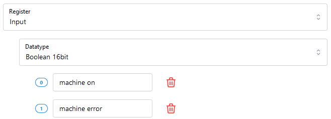
If the value changes to 1100000000000000,
the machine_error tag will change to 1.
The tag on the rule will be ignored.
Address
The address to read from.
Poll rate
The time between measurements, in seconds.
Transform values
Transformations clean and convert the values of this rule before they are stored. Every new rule starts with a Deduplication transformation, so unchanged measurements are not stored over and over. Counters, timers, text to value and more are also available. Read all about transformations here.
Override Slave ID
When multiple slave devices are on the same IP address or COM port, the rule can be pointed to the right device. If the device has another Endianness or another Word order, this can also be changed here.
Labels
You can override or add labels per rule. Read more about this here.
Test rule
A new window will open with the test results.
Some Modbus clients don’t accept two or more connections. This means that after the connection is started, testing a rule will stop working, because the connection is already taken by the Collector.